Understanding Construction Documents in Architecture
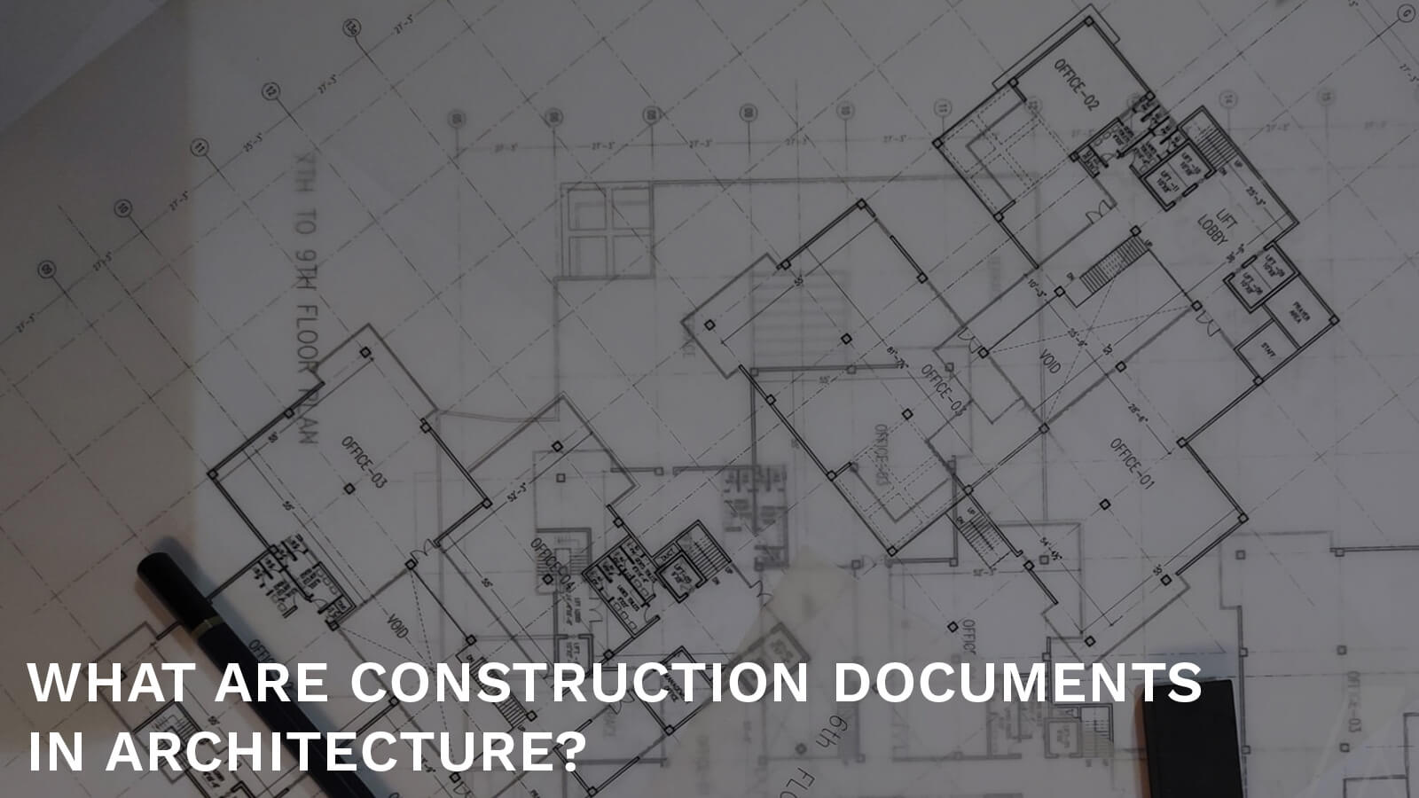
The architects designing your next house or commercial building will always create documentation for the construction team, either hard copy or digital, to refer to. This documentation, typically known as construction documents or construction drawings, becomes the guideline for the construction process.
Each step is discussed and noted within these documents, which are then to be followed at each stage of construction.
This ensures that no errors occur during the construction process, thereby saving time, money and resources. Another essential reason for beginning with the documents is to ensure the necessary permits are gathered, and building codes are followed. From a legal aspect, this step is crucial before laying the foundation of the building.
The Process of Architectural Documents or Construction Drawings:
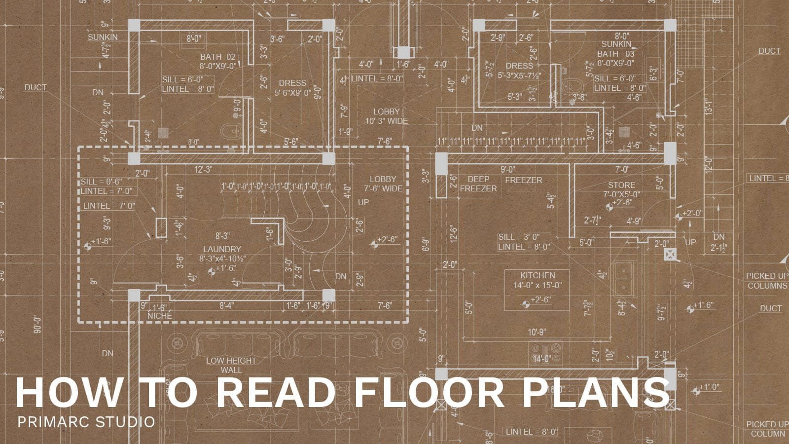
To read construction plans effectively, one must understand the various components that make up the plans. These components include plans, elevations, sections, and details. Plans provide an overhead layout of the building, showing the location of walls, doors, windows, and other features. Elevations show the building from the front, side, and back, providing information on the height and appearance of the building. Sections detail how the building is assembled, including foundations, framing, and finishes. These details offer insights into specific construction techniques and materials used in the building. Additionally, architects may create 3D models of the building to aid visualization and planning.
Understanding these components is essential for interpreting and comprehending construction plans effectively. However, to truly master the reading of construction plans, one must also grasp the technical nuances:
Elevation: The elevations show the building from the front, side, and back and provide information about the height and appearance of the building.
Section: The sections show how the building is assembled, including details about the foundations, framing, and finishes. These details provide more information about specific construction techniques and materials used in the building.
Dimensioning Practices
- Consistent Dimensioning: It’s crucial to use consistent dimensioning from a fixed reference point, such as the centerline or exterior/interior finish. This ensures clarity and reduces errors across different drawings.
- Hierarchy of Dimensioning: Prioritize dimensioning important information and avoid repeating dimensions of the same element across multiple drawings.
- Type of Dimensioning: Employ horizontal dimensioning in plan drawings and vertical dimensioning in section and elevation drawings.
Drawing Scales and Line Weights
- Appropriate Scales: Choose an appropriate drawing scale for the information being presented. For instance, overall site plans may be presented at a scale of 1”=40’-0”. Floor plan drawings might use a scale of 1/16”=1’-0”, or 1/8″=1’-0” for smaller buildings. Construction details, which show a lot of information in one drawing, may be at a scale of 1-1/2″=1’-0” or even larger.
- Line Weights: Always consider line weight appropriate to the scale of the drawing. This helps differentiate between different types of elements and ensures that the plans are easy to read.
Annotations and Specifications
- Annotations: Annotations appear in almost every drawing and are used to convey concise information about the materials or components of the building system presented.
- Specifications: These short descriptions are elaborated in the specifications, providing a more comprehensive explanation of the materials, components, and building systems, as well as the installation and execution procedures for each.
Verification Processes
- Accuracy Checks: Always double and triple check dimensioning before submitting construction documents to avoid any costly mistakes during construction.
When creating these various types of construction drawings, it is crucial to consider the line weight appropriate to the scale of each drawing. Line weight plays a significant role in the clarity and effectiveness of a drawing. It should vary across different drawing scales to ensure that every detail is properly highlighted and easily understandable. This consideration helps in maintaining the technical accuracy and visual integrity of the architectural plans.
In addition to the drawings, architects may also create 3D models of the building using CAD software to visualize the design and help with the planning and construction process. These models can be used to create virtual walkthroughs of the building, as well as to create construction documents and other materials.
Understanding the Importance of Scale in Construction Drawings
An essential aspect of creating these construction drawings is choosing an appropriate drawing scale for the information being presented. This decision is critical as it influences the clarity and usability of the drawings. For example, overall site plans may be presented at a scale of 1”=40’-0”, which provides a broad overview. In contrast, floor plan drawings, which require more detail, may be presented at a typical scale of 1/16”=1’-0”, or 1/8″=1’-0” for smaller buildings. More intricate construction details, which show a lot of information in a single drawing, may be presented at a scale of 1-1/2″=1’-0” or even larger.
It is also crucial to consider the line weight appropriate to the scale of the drawing. The variation in line weight helps differentiate between various elements and ensures that the drawings are easy to read and interpret. Different scales might require adjustments in line weight to maintain visual clarity and effectiveness.
Overall, the process of creating construction drawings involves a combination of design skills, technical knowledge, and communication skills, as the architect must be able to translate their design ideas into clear and accurate drawings that can be used to construct the building. It serves as an important checklist to ascertain everything is in order. This meticulous attention to scale and detail underscores the importance of precision in architectural planning and execution.
“In pure architecture, the smallest detail should have a meaning or serve a purpose.” – Augustus W. N. Pugin
Reasons for Creating Construction Drawings:
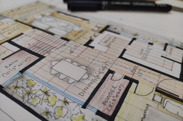
Construction drawings are an essential part of the design and construction process for a building. They serve several important purposes:
Clear Communication in construction drawings.
Construction drawings provide a clear and visual way for the architect to communicate their design ideas to contractors, engineers, and other stakeholders. They show how the building is intended to be constructed, which helps ensure it is built according to the architect’s vision.
Ease in Coordination:
Construction drawings or documents help coordinate the work of different contractors and trades, such as electricians, plumbers, and HVAC technicians. By providing a detailed and accurate representation of the building’s design, construction drawings help ensure that all the different parts of the building are properly integrated and that the building is constructed efficiently and safely.
General Documentation:
Construction documents or drawings are also a permanent record of the building’s design and construction. Accuracy in details and dimensions of the building is made possible via professionally drafted architectural construction documents. They provide a reference for future repairs and renovations and can be used to resolve disputes or clarify design intent.
Overall, construction drawings play a crucial role in the design and construction of a building, helping to ensure that the building is built according to the architect’s vision and meets the needs of its users.
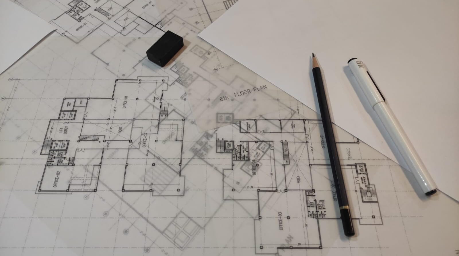
The Beginner’s Checklist for Architectural Construction Documents:
You want to make sure you have the basics covered in your documentation by keeping the following items in mind as well:
- A0 sheets: Permits and general information
- A1 sheets: Demolition plans – If it is a renovation project.
- A2 sheets: Floor plans – Based on the specification of your building floors.
- A3 sheets: Elevations
- A3 sheets: Cross Sections of the building. (You can see the cross-section points and directions in the floor plans.)
- A4 sheets: Finishing plans (ceiling, lighting, etc.)
- A5 sheets: Interior elevation
- A5a sheets: Interior details
- A6 sheets: Schedules of openings like windows, doors and other features.
A7 sheets: Notes or any other details.
Structural drawings. (These drawings are issued by a structure engineer and attached with the architecture drawings to allow ease in coordination)
Mechanical drawings. (Drawings issued by mechanical engineer)
Electrical drawings. (Drawings issued by electrical engineer)
Plumbing drawings. (Drawings issued by public health engineer)
In construction drawings, the letters G, C, L, S, A, F, P, M, E, and T represent specific aspects of a project, helping professionals from various fields navigate and understand the plans efficiently.
G stands for General Documentation, which encompasses the sheet list, symbols, summary, life safety, and code analysis, providing a foundational overview for all stakeholders.
C, representing Civil, details the engineering work related to the site and environment, crucial for the project’s external factors.
L is for Landscape, detailing the design and planning of outdoor spaces.
S stands for Structural drawings, crucial for understanding the framework that supports the building.
A represents Architectural design, showcasing the aesthetic and functional elements of the project.
F stands for Fire Protection, outlining systems designed to protect the building from fire hazards.
P denotes Plumbing drawings, essential for the layout and installation of pipes and water systems.
M stands for Mechanical drawings, which include heating, ventilation, and air conditioning systems, critical for maintaining indoor environment quality.
E represents Electrical drawings, detailing the wiring and power layouts.
T for Telecommunications, highlighting the infrastructure for communication devices and services.
Each of these letters not only guides specific professionals in their tasks but also enhances clear communication and ease in coordination among the diverse teams involved in a construction project. The final two digits of the sheet number in construction drawings after letters like A, E, and other letters, play a crucial role in indicating the specific sequence within each discipline. These numbers, ranging from 01 to 99, help organize the drawings systematically.
The other types of equally important but not necessarily related documents, such as bidding documents, contracts between all parties, project management agreements, cost estimates, legal permits, etc., are not classified as construction documents. However, clients would be wiser to keep them all separately safe.
Overall, it is imperative to note that the process of documenting architectural projects has varying degrees of differences among architects. There is a notable distinction between residential and commercial documentation, mainly due to levels of complexity, code, and regulations.
However, if, due to circumstances, the client is unable to uphold this responsibility, they can hire professional architects to represent their best interests. The architects at Primarc Studio consider it an important part of the construction process. This is why they are conscious of exhibiting the highest level of care and attention to the clients and constructors of their projects.
“A designer is a planner with an aesthetic sense.” – Bruno Munari.
Notable Examples from Industry Professionals
Jill Sorson Kurtz:
Jill’s portfolio includes detailed construction documents that emphasize innovative design and sustainability.
John Anthony Drafting and Design:
Known for precise and thorough drafting, John Anthony provides comprehensive drawings and specifications for residential and commercial projects.
Tesla Outsourcing:
This company specializes in outsourcing detailed construction documentation, offering high-quality plans and specifications tailored to client needs.
William Webb Architect:
William Webb’s examples include extensive architectural drawings and detailed specifications that highlight both aesthetic and functional elements of construction.
Frequently Asked Questions About Construction Documents and Drawings
Question: How does scale choice impact other elements of the drawings, such as line weight?
Answer: The choice of scale affects the line weight used in drawings. As the scale increases to show more detail, thicker line weights are typically necessary to maintain visual clarity and distinguish between different elements effectively.
Question: What specific areas of construction planning and execution are categorized under each letter?
Answer: The letters categorize construction documents into areas such as civil engineering (Civil), landscape design (Landscape), structural engineering (Structural), architectural design (Architectural), fire safety measures (Fire Protection), plumbing systems (Plumbing), mechanical systems (Mechanical), electrical systems (Electrical), and telecommunications infrastructure (Telecommunications).
Question: What are some additional disciplines that can be included in construction drawings?
Answer: Construction drawings benefit from various specialist input for a complete picture. Consider including:
Environmental/Hazardous Materials: Safe handling and regulations for on-site substances.
Geotechnical Engineering: Soil conditions, foundations, and earthworks for structural integrity.
Interior Design: Layouts, finishes, and materials for desired aesthetics and functionality.
Distributed Energy Systems: Plans for renewable energy installations like solar panels.
Operational Plans: Construction schedules, workflows, and other strategies for project efficiency.
Shop Drawings/Distribution: Detailed fabrication and installation requirements from contractors.
Question: What are the different types of drawings indicated by the numbers 0 through 9 in construction drawings?
Answer: In construction drawings, each number from 0 to 9 signifies a specific type of drawing or information. Here’s a breakdown:
0 – General Drawings: These include legends, symbols, and general notes that provide a foundation for understanding the other drawings.
1 – Plans: These are overhead views that show the layout of spaces and placements of elements.
2 – Elevations: Elevations are side views that illustrate the vertical dimensions and relationships.
3 – Sections: Sections cut through the building to reveal internal features and structural components.
4 – Large Scale Drawings: These provide detailed views of plans, elevations, and sections for more intricate areas.
5 – Details: Detail drawings zoom in on specific parts to show precise construction methods or connections.
6 – Schedules and Diagrams: These drawings include schedules of fixtures, finishes, and diagrams for systems like electrical or plumbing.
9 – 3D Drawings: This category includes isometric, perspective, and rendered drawings, offering a three-dimensional view of the construction.
Numbers 7 and 8 are typically reserved for user-defined drawing types, allowing flexibility for unique project needs.
Question: What are some standard methods for dimensions in construction plans?
Answer: Consistent dimensions in construction plans is key for accuracy. Here’s how firms achieve this: Establish a fixed reference point for all dimensions. Use a hierarchical system to highlight only crucial dimensions. Avoid redundant dimensions across drawings. Use specific formats for horizontal and vertical dimensions in different views.
Finally, meticulously review dimensions before finalizing construction documents. These practices ensure clear, concise, and practical architectural drawings for successful project execution.
Primarc Studio Architects
The Primarc Studio editorial team consists of architects and designers specializing in modern residential projects, interior designs and commercial designs across Pakistan. Together, we share insights on design trends, construction costs, and project case studies.


